1. Overview
Software requirements:
-
Windows 10 or 11 (32 or 64 bit)
-
.NET Core 5
2. General usage
IED Configurator is a user-friendly tool to configure IEC 61850 intelligent electronic devices (IEDs). It allows configuring address parameters, IED names, control blocks, and data sets. Most configurations can be done by simple drag-and-drop operations. It can handle CID and SCD files. It is also possible to import or export IED configurations from CID and SCD files.
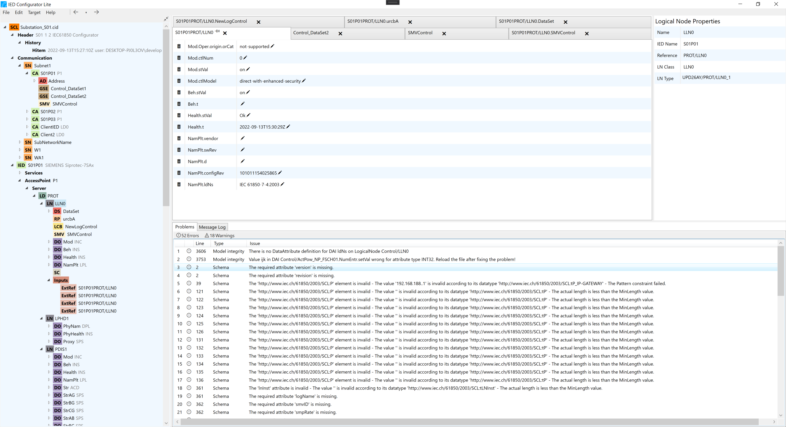
3. The Main Window
On the main window, the user can have an overview of all the intelligent electronic devices (IEDs) and their components, data types, communication configuration, and header of the configuration document. A panel with properties is displayed showing all information for each control selected and log messages with the timeline of the configurations as well as warnings and problems within the configuration file can be found in that window. The window also contains a configuration panel that provides the means to configure the controls from the document tree while having an overview of all the information needed on just one screen.
From the tree view, the user can have access to IED Protocol Settings and Upload Configuration File windows through the context menu in the IED tree node, which also provides many other options of configurations such as Rename, Add Connect Ap, Convert to Config File and Delete. New IEDs can be added by right-clicking on the document node and selecting “Add IED“. Another important feature to configure the file is the possibility to drag and drop IEDs from other documents, which the tools make it possible to safely merge the IED with its Data Types, Subnetwork, ConnectedAp, and all the sub controls that belong to the source IED into the target document.
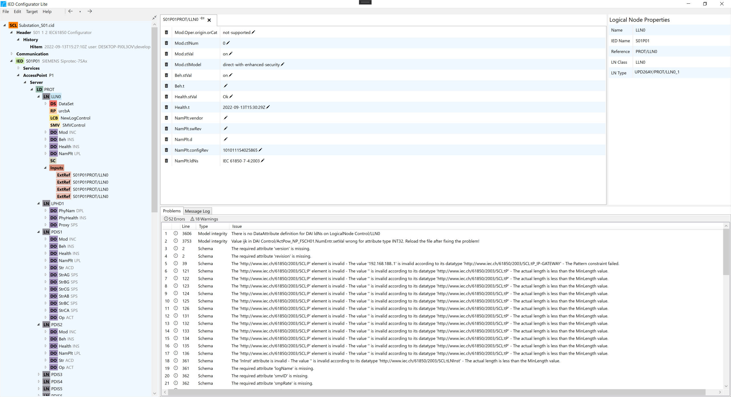
3.1. Tree view (Configuration)
-
Single clicking on each node of the tree shows the Properties in the last right column.
-
By double clicking on the nodes: Data Set, Logical Node, Data Object, Report Control, Log Control, GSE Control, SMV Control, Setting Controls, Inputs, External Reference, SMV Control, GSE, SMV, Hitem the user can open the configuration tab.
-
By right-clicking on the Data Set, Report Control, Log Control, GSE Control, Log Control, SMV Control, GSE, SMV the user has configured, rename, or delete options.
-
By right-clicking on the Setting Control, Inputs, and External References (ExtRef) the user has the options configured and delete.
-
By right-clicking on Data Objects the user only has the configure option.
-
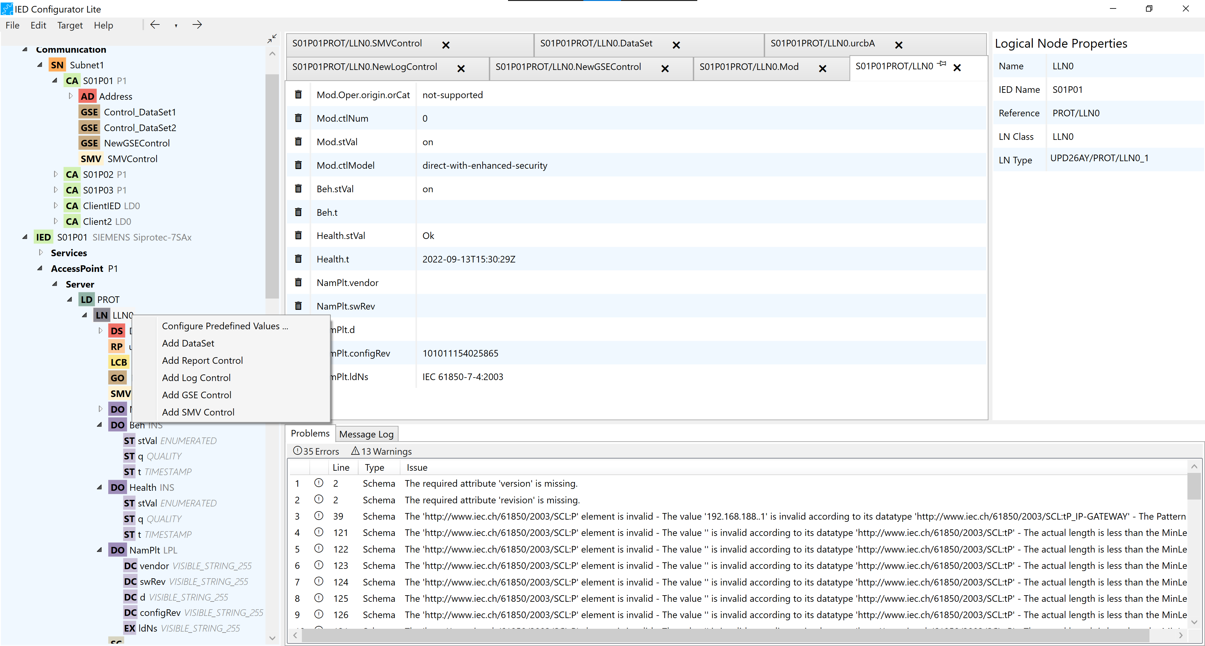
By right-clicking on Logical Nodes, the user can either configure predefined values or add: Data Set, Report Control, Log Control, SMV Control, GSE Control, Setting Control, and Inputs.
4. Configuration
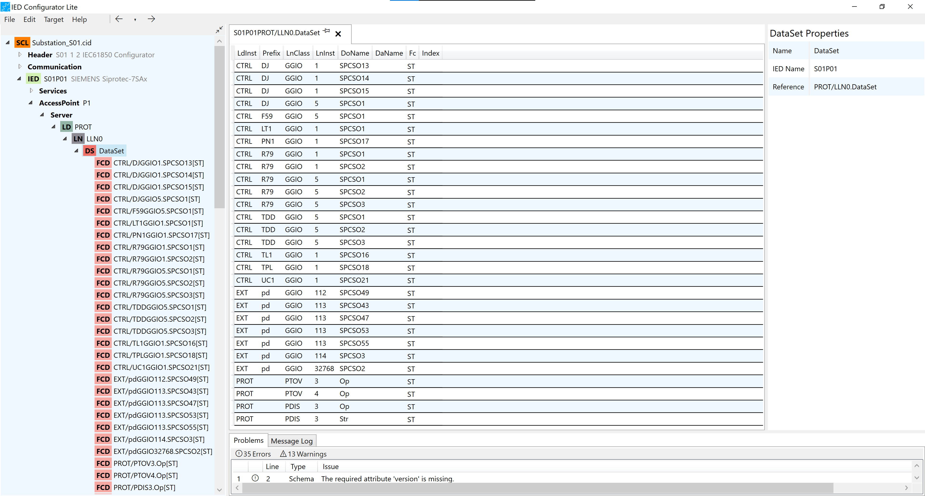
4.1. DataSet
-
Each Data Set consists of a number of FCD (Functionally Constrained Data).
-
To add a new FCD, the user needs to drag and drop a DO (Data Object) or a DA (Data Attribute) in the DataSet configurator panel, or in the DataSet node on the IED tree.
-
By right-clicking on the Data Set, the user has configured, rename or delete options.
-
Each Functionally Constrained Data is represented by a row in the configuration tab.
-
In the configuration tab, each row can be selected. After selection, delete and move actions could be implemented on the selected row.
-
Multiple rows can be selected. Move and Delete actions could also be applied to a number of selected rows.
4.2. Predefined Values
-
The Predefined Values configurator panel exists for Logical Nodes and Data Objects.
-
Predefined Values can be added or deleted in the Predefined Values configuration tab. The user can add new ones by dropping Data Attributes in the configurator or clicking on values that appear in grey in the predefined values configurator, those are Data Attributes that already has values in the Logical Node but are not yet added to predefined values.
-
Data Objects could also be dragged and dropped directly to the Predefined Values configuration, then the desired Data Attribute to be added has to be selected from the dropdown menu.
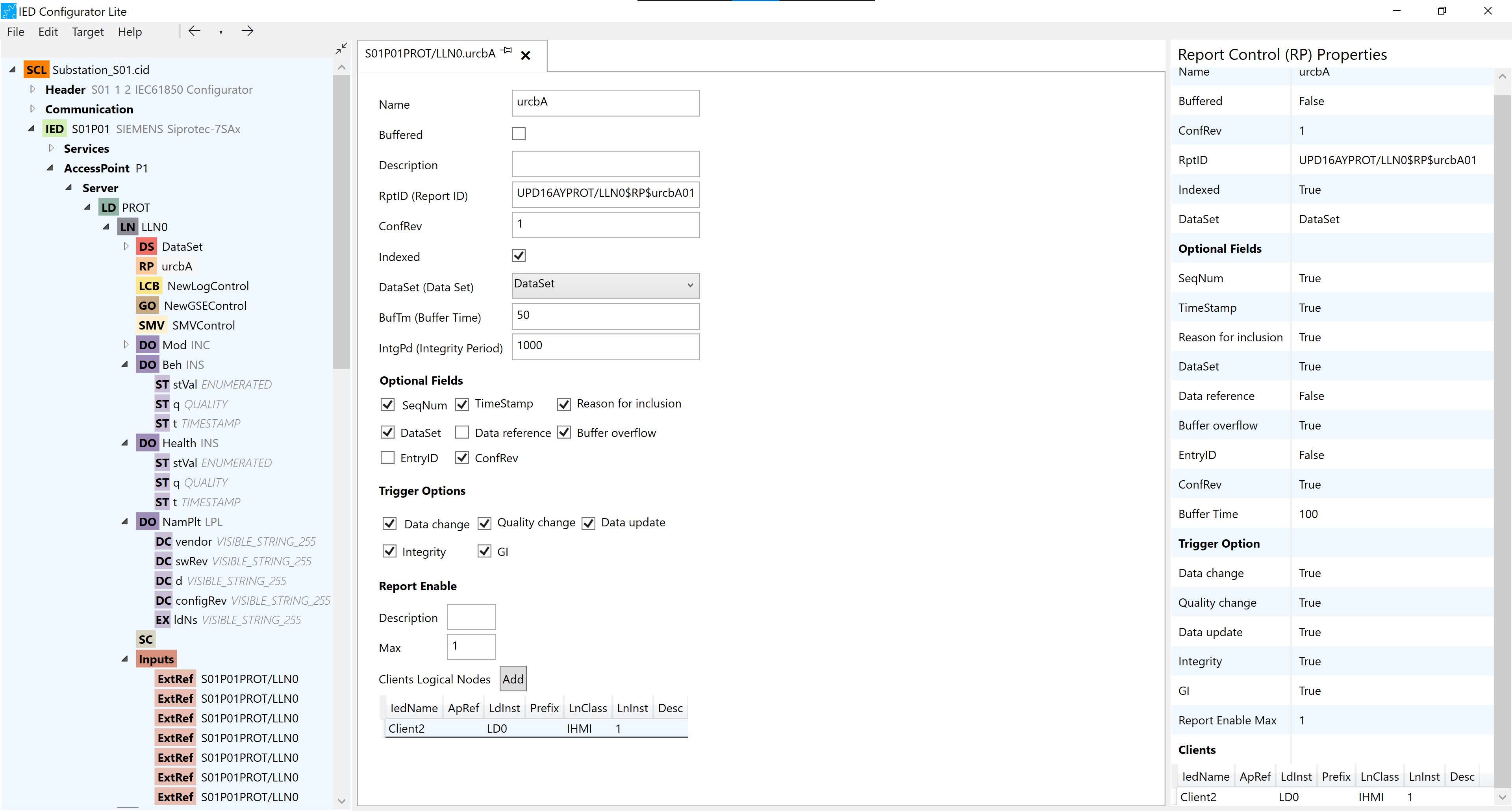
4.3. Report Control
-
In Report Control Configuration
-
Details such as Name, Buffered and etc. can be changed.
-
Optional Fields and Trigger Options could be selected.
-
-
Report Controls can be dragged and dropped into inputs. This action adds details to External References.
-
Client Logical Nodes can be dragged and dropped in the Report Enable section in the configuration tab.
-
The maximum number of the Clients Logical Node can be defined in the Max box Report Enable section in the configuration tab.
-
The number of client Logical Nodes can also be increased manually by pressing the Add button in the Report Enable section in the configuration tab.
-
If the number of the Client Logical Nodes added manually is bigger than the Max set an error is shown in Problems Log.
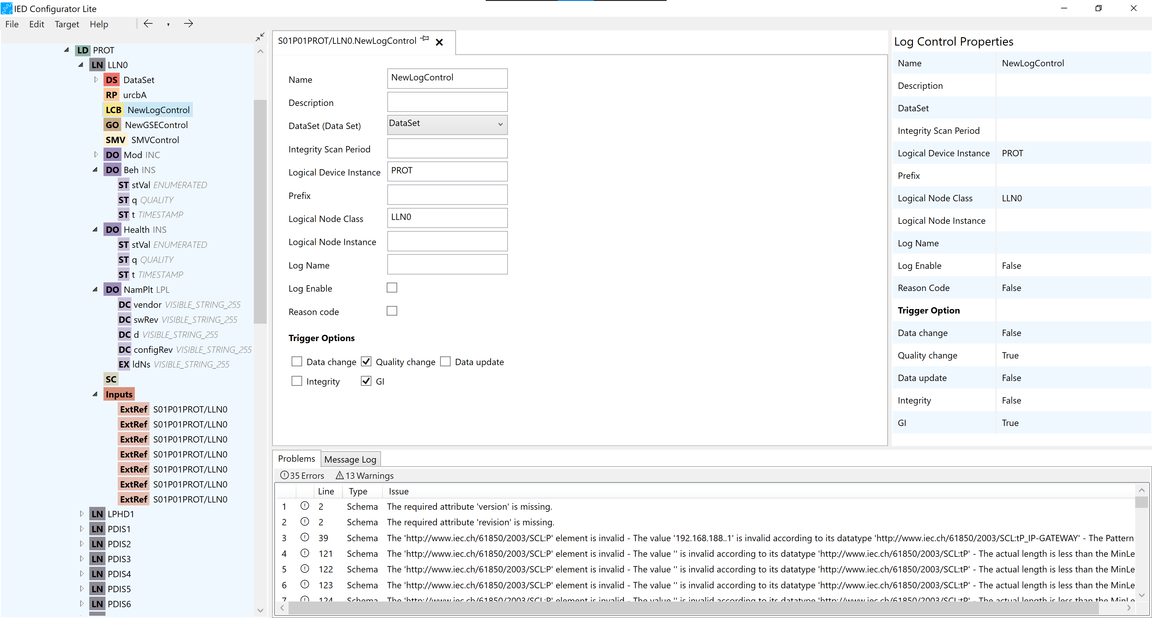
4.4. Log Control
-
Details such as Name, Description and etc can be changed in the configuration tab.
-
Trigger options could be selected and deselected in the configuration tab.
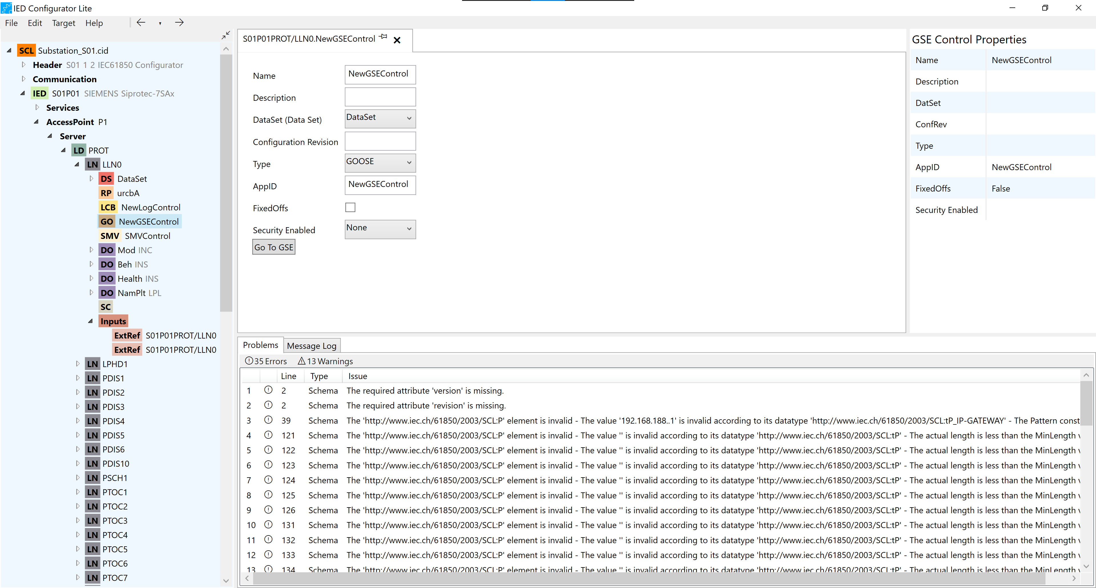
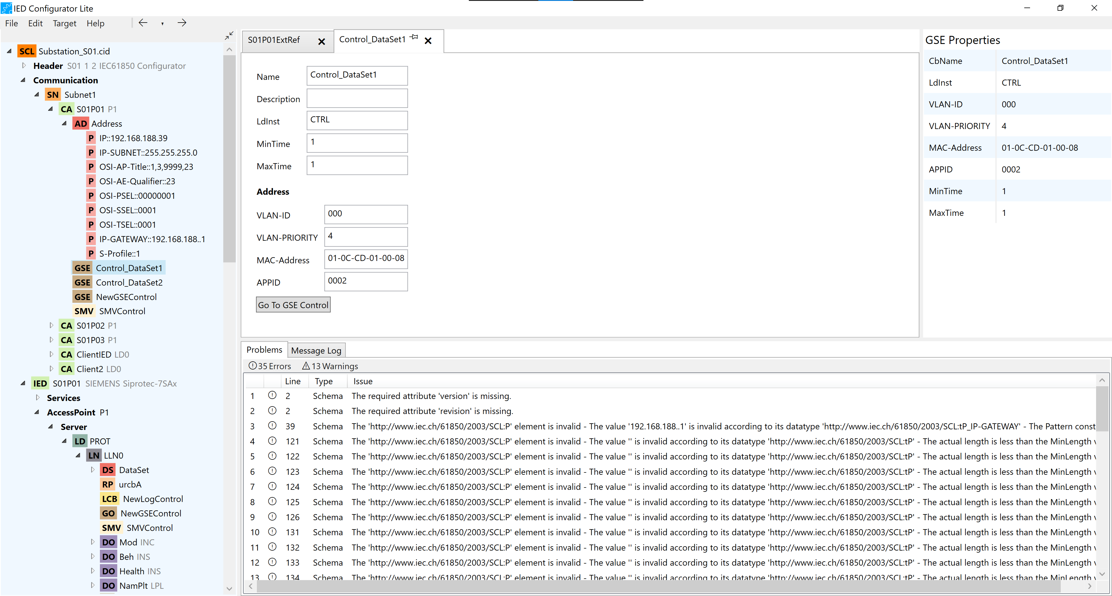
4.5. GSE Control
-
Details such as Name, Description and etc. could be changed in the configuration tab.
-
By pressing the “Go to GSE“ button, the user can switch between the GSE Control on the Server and the corresponding GSE on the Communication.
-
GSE Control can be dragged and dropped in Inputs (to either create an ExtRef or make changes to an existing one).
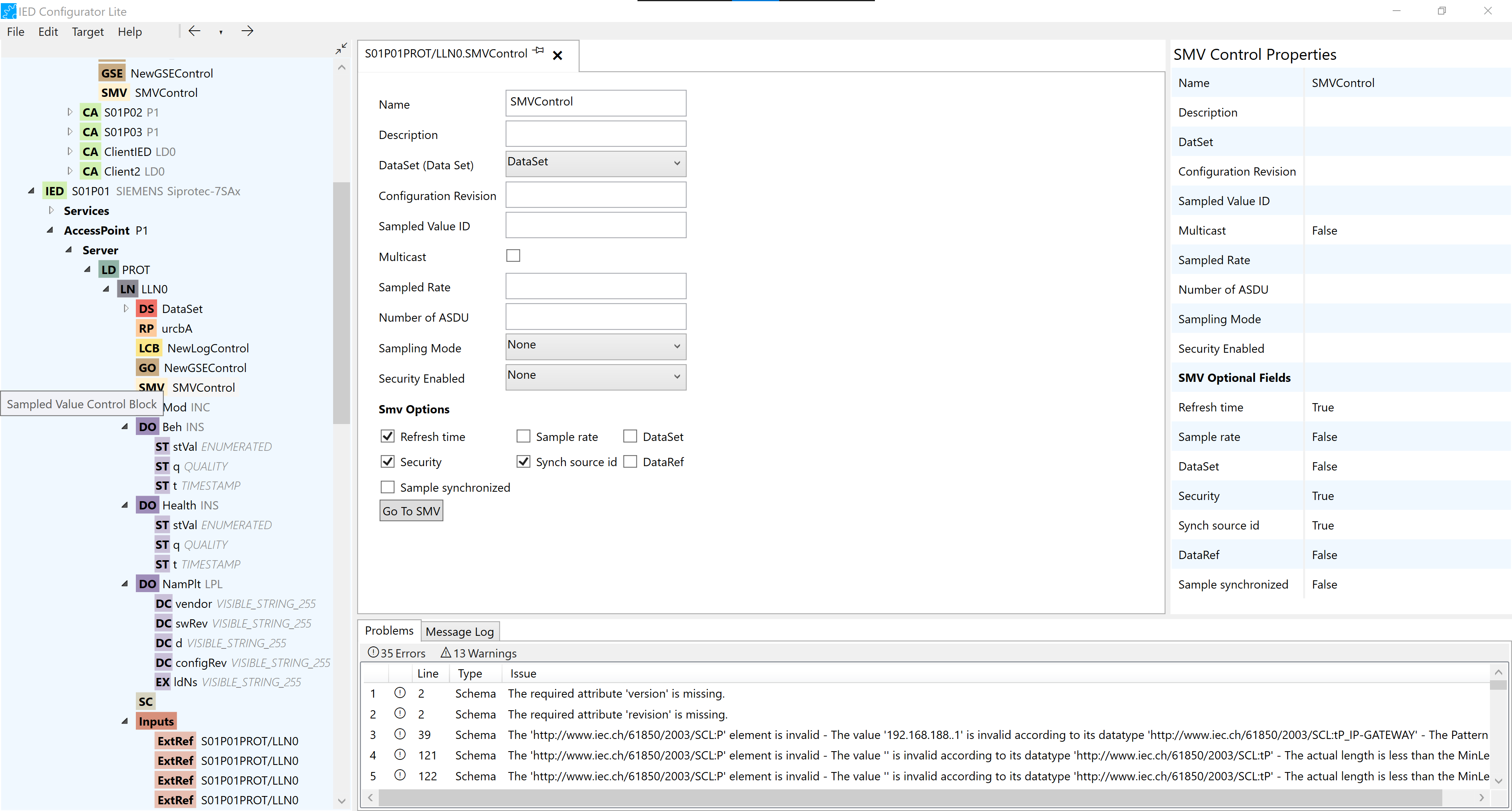
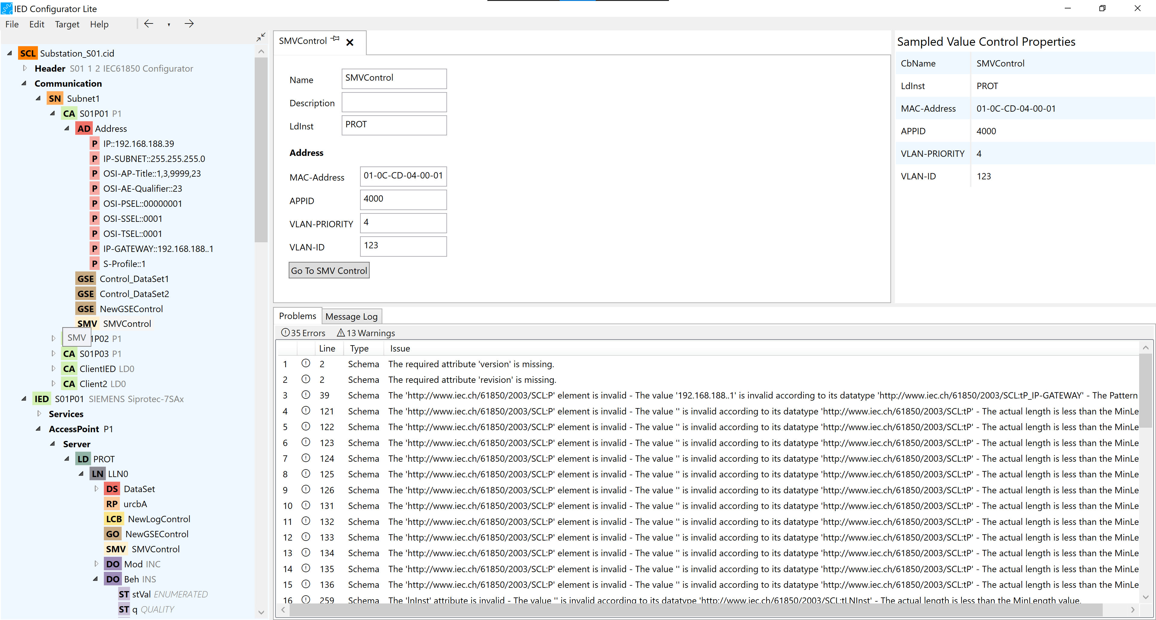
4.6. SMV Control
-
Details such as Name, Description and etc. could be changed in the configuration tab
-
By pressing the “Go to SMV“ button, the user can switch between the SMV on the Server and the corresponding SMV on the Communication.
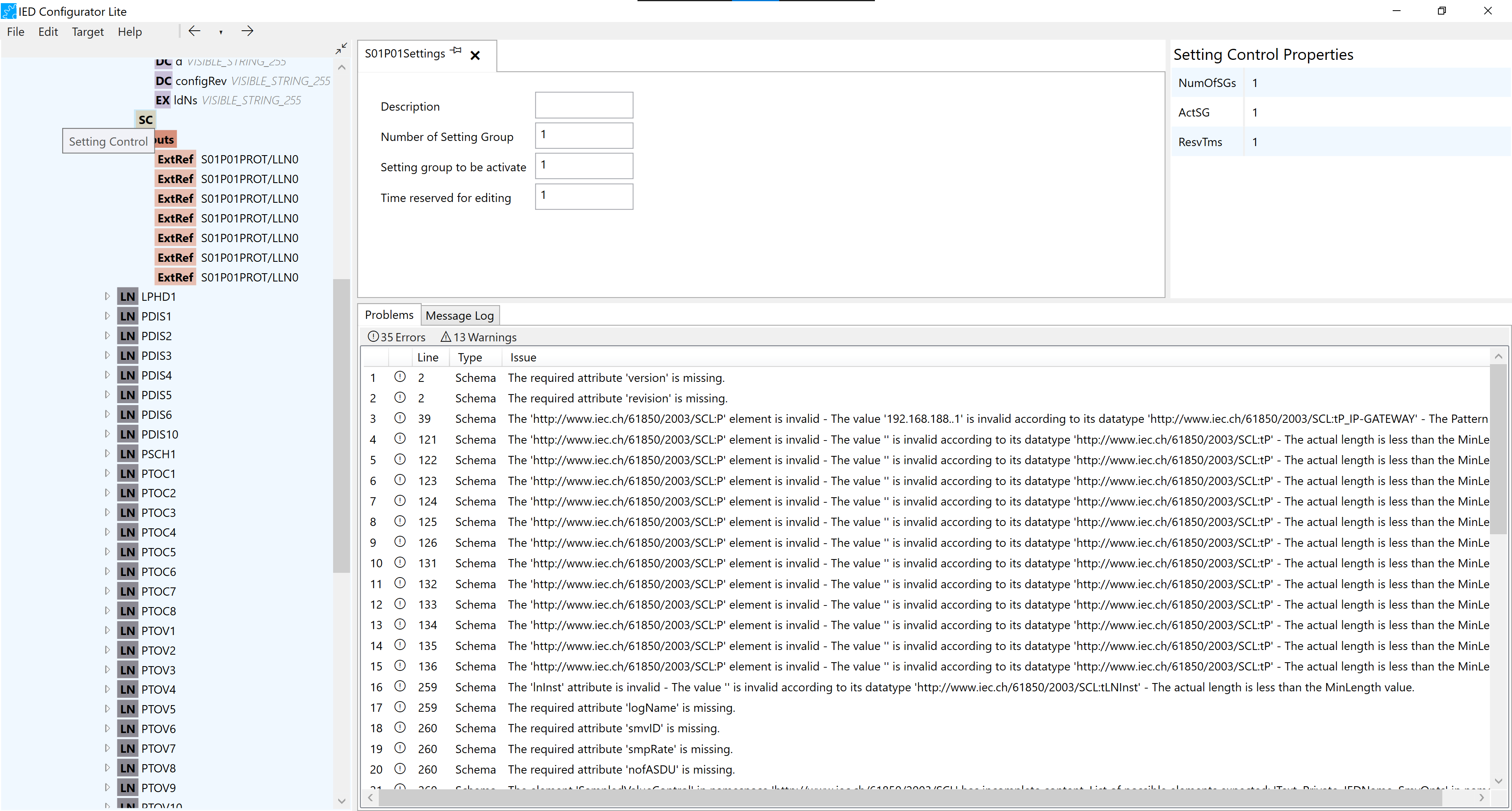
4.7. Setting Control
-
In the Setting Control configuration tab, the Description and Time reserved for editing can be changed.
-
The number of Setting Group and Setting group to be activated can also be changed but the range should be considered carefully.
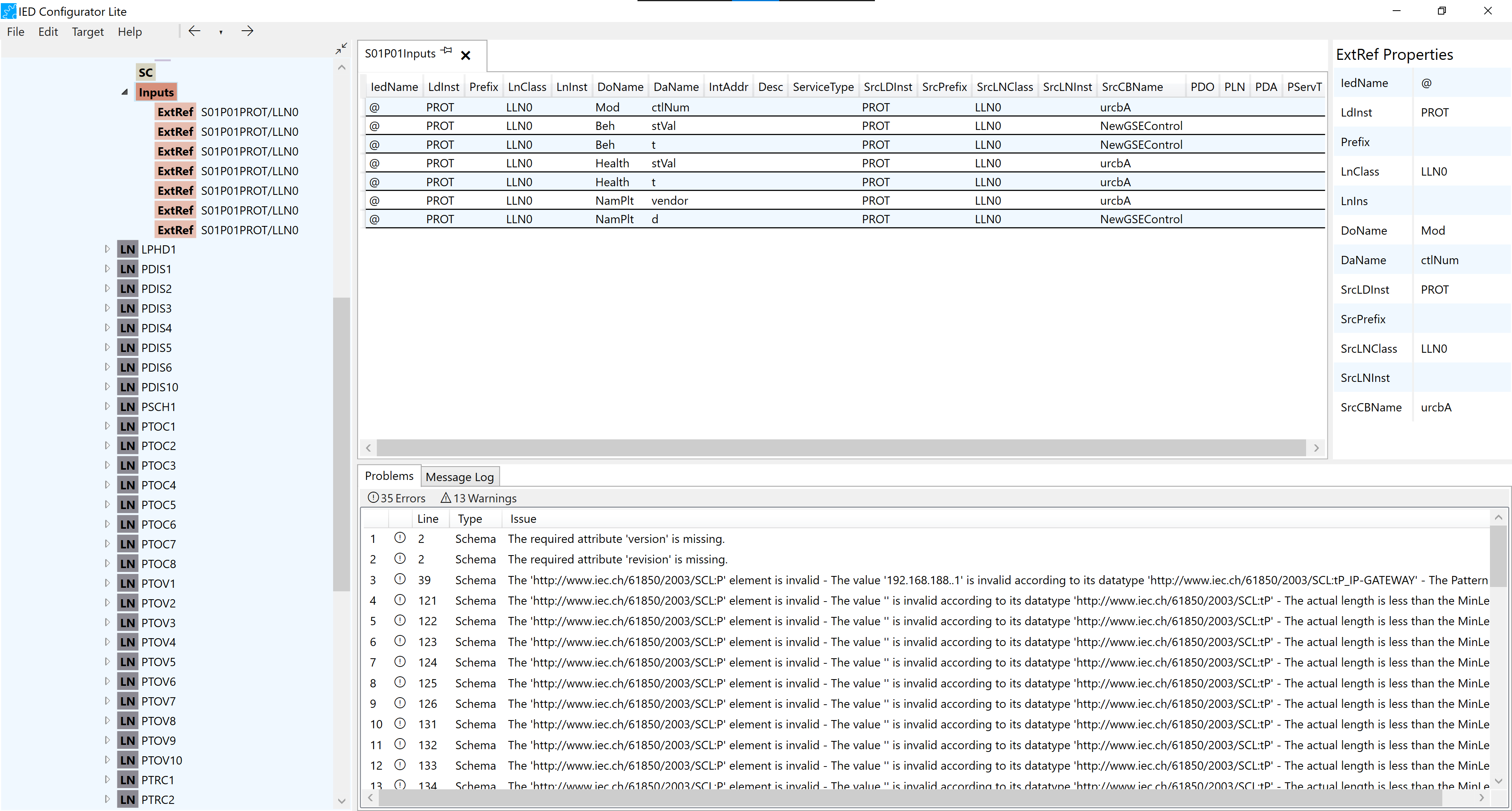
4.8. Inputs
-
Each row of the Inputs configuration tab represents an External Reference. This has two main sections: Data Attributes and Report Controls or GSE Controls.
-
Report Controls, Data Attributes and GSE Controls can be dragged and dropped into the Inputs configuration tab and in the Inputs node in the IED tree. If they are dragged and dropped directly a new ExtRef is created.
-
Report Controls and Data Attributes can also be dragged and dropped to the existing ExtRefs to change or complete them.
-
Data Objects can also be Dragged and dropped in the Inputs configuration tab but the desired Data Attribute should be selected from the dropdown menu.
-
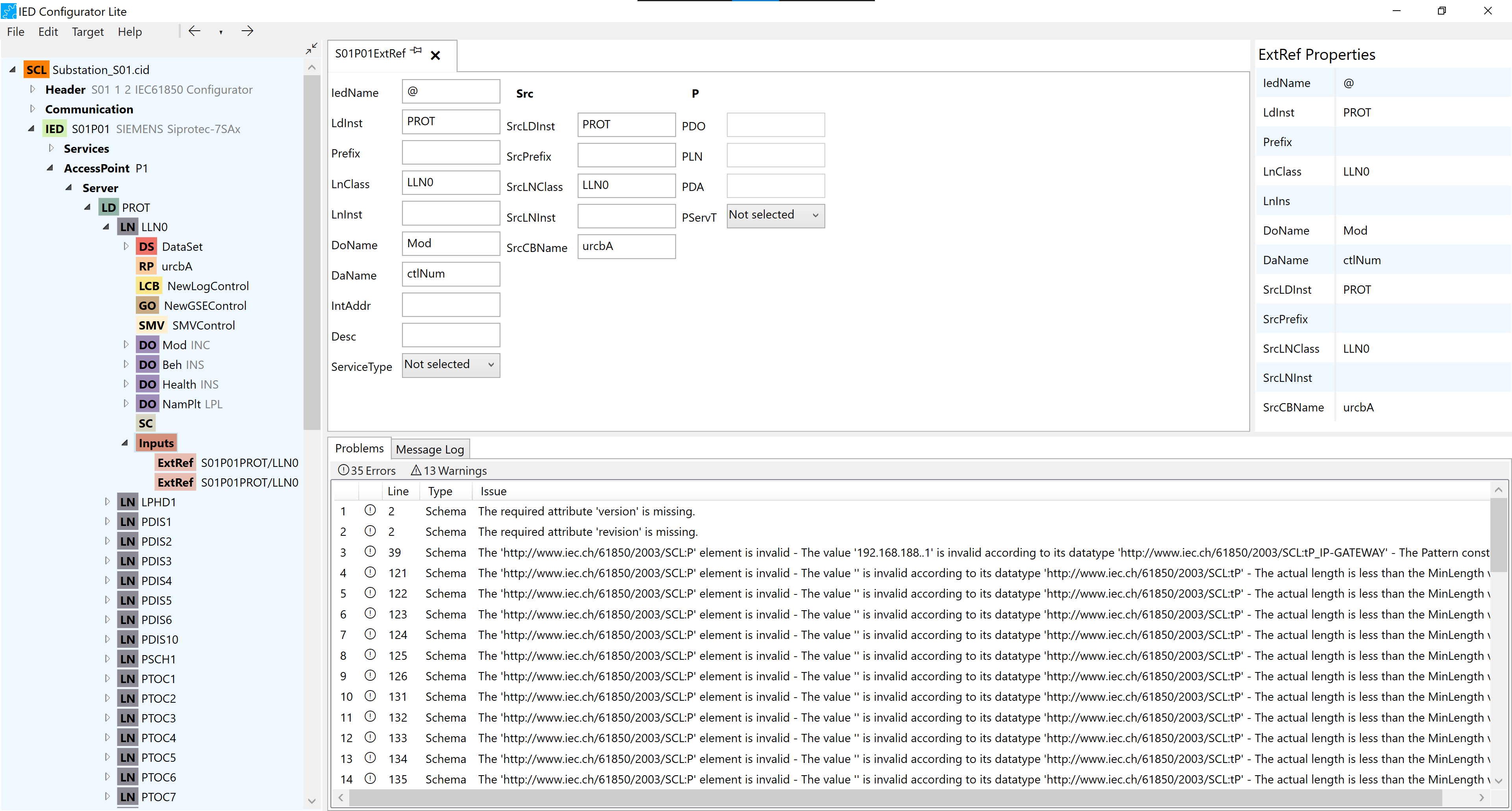
ExtRef
-
In ExtRef configuration tab, details such as Ldlnst, prefix and etc. can be changed.
-
Src details can be changed.
-
Report Controls, Data Attributes and GSE Controls could also be dragged and dropped in the ExtRef configuration tab in order to be added to the Extref or changed.
-
4.9. On Communication
-
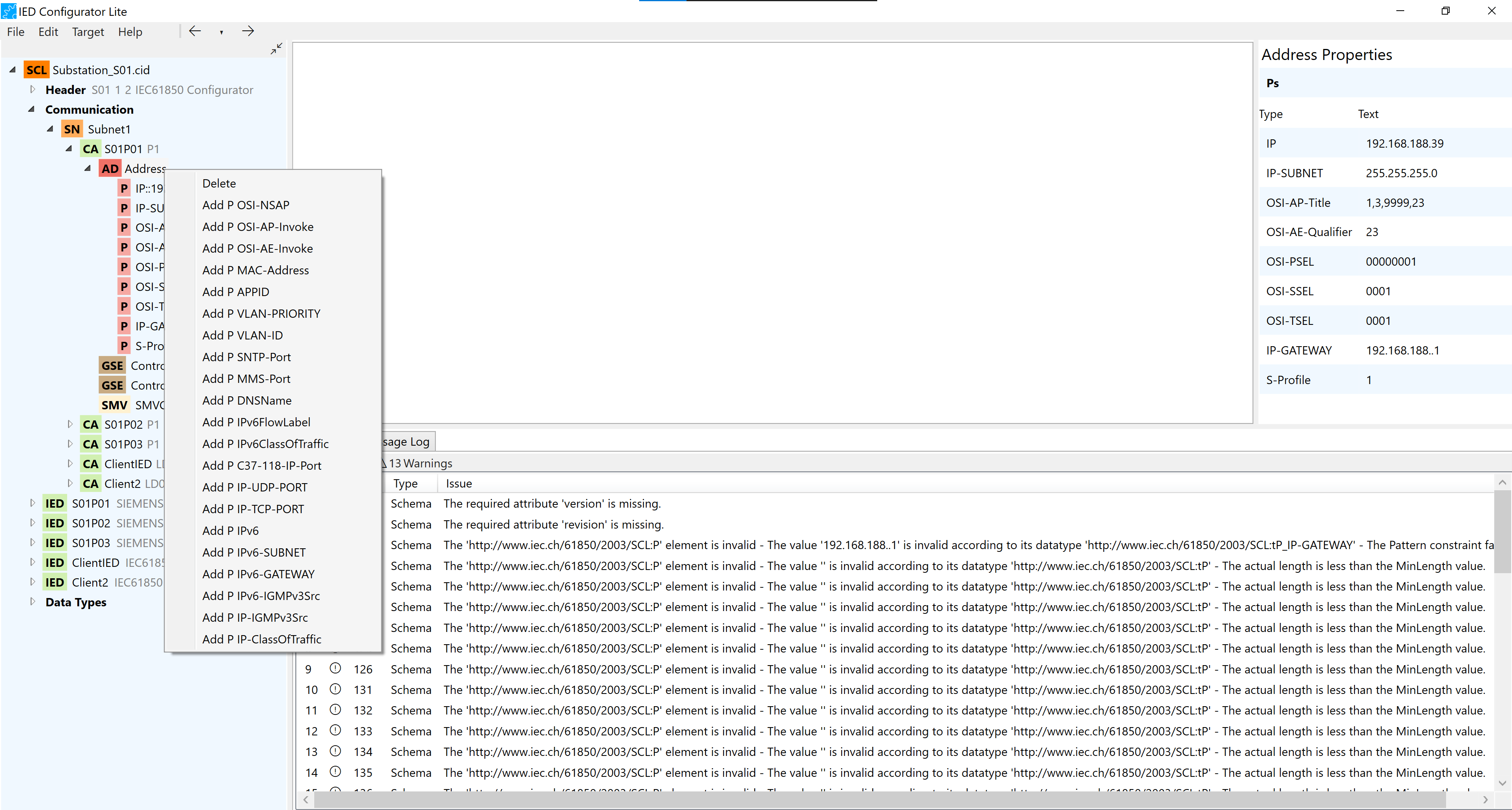
Address
-
Each Address node consists of a number of P Addresses.
-
By right-clicking on the Address, the user can either delete the node or add new possible P Addresses to it.
-
P
-
Each P address can be configurated by double-clicking or right-clicking and choosing “Edit address”.
-
-
-
GSE
-
By pressing the “Go to GSE Control“ button, the user can switch between the GSE on the Communication and the corresponding GSE Control on the Server.
-
By pressing the “Go to GSE Control“ button, the corresponding GSE Control configuration tab on the server is opened.
-
-
SMV
-
By pressing the “Go to SMV Control“ button, the user can switch between the SMV on the Communication and the corresponding SMV Control on the Server.
-
By pressing the “Go to SMV Control“ button, the corresponding SMV Control configuration tab on the server is opened.
-
5. Problems/Message log
-
Issues with the configuration of the controls are reported to the user through the issues table, on the main window with warnings that can be removed after the problem is solved, making the configuration of the document more reliable when the user can track the work and solve integrity problem during the running time of the tool.
-
This Issues also display warnings and errors found in the file when cross-checked with the SCl Schemas and NSDs.
-
The user can revalidate the documents by right-clicking in the SCL node tree.
6. Merging files
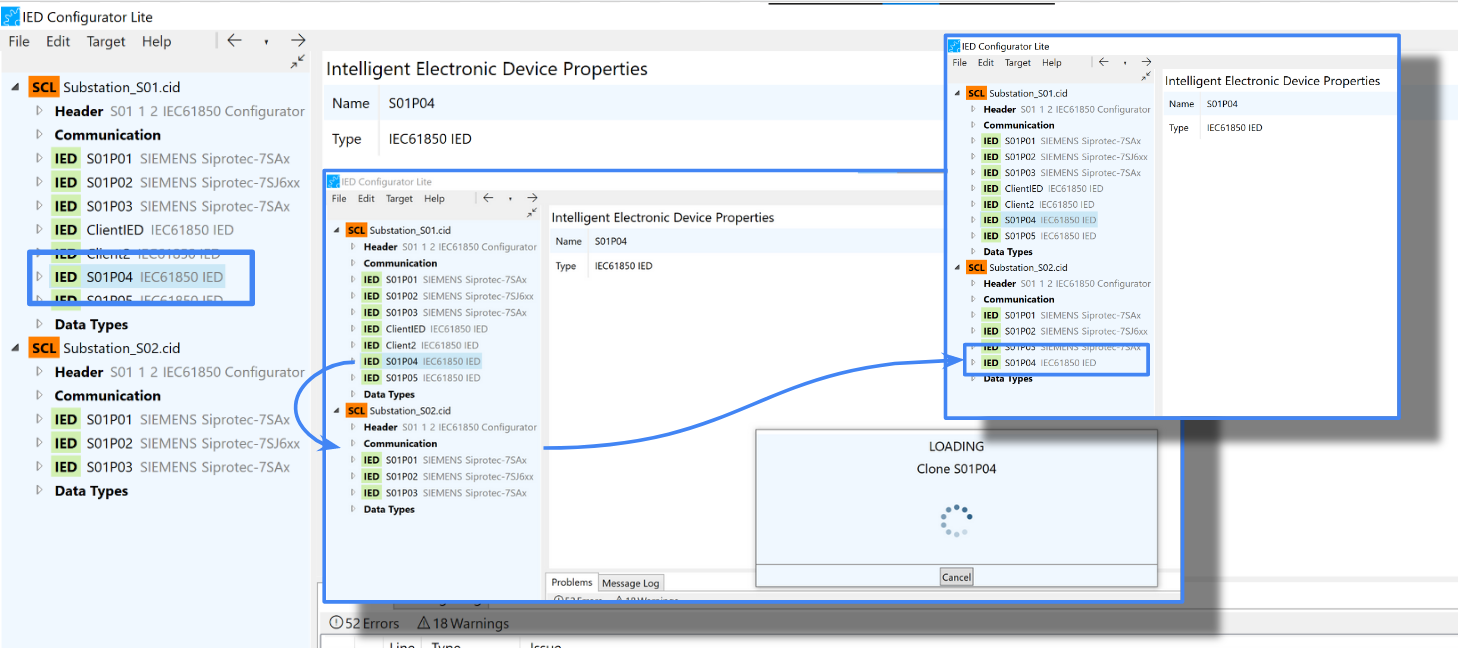
Documents can be merged by dragging and dropping IEDs from other SCL documents. If the source IED has a Subnetwork, it will also be added to the target documents, along with the DataTypes. If already exist an IED with the same name on the target documents, the new IED is renamed. If there is a Subnetwork on the target document with the same reference as the one from the source IED, then the new IED is added to the existing subnetwork.
7. Configure a server
7.1. Set IED name
Double-click on the IED name or right-click on the IED tree for context menu renaming to rename the IED.
7.2. Set IP address parameters
From the Communications/Connected APs/Address node of the document tree, IP addresses can be configured. Right-click on the Address node and select the IP address you want to add. Double-click on the IP value or right-click in the IP node and select "Edit Address" to modify the value.
8. Configure a client
8.1. Configure report subscriptions
-
The Client Logical Node element defines the name of an LN in the system, which is a client to the Report Control.
-
If Report Enable on the Report Control is non-existent, the user has to edit the Max properties on Report Enable and then configure the Client Logical Node.
-
To configure the Client logical Node the user can either click on the button to add and fill the row manually or drop a logical node from the tree view.
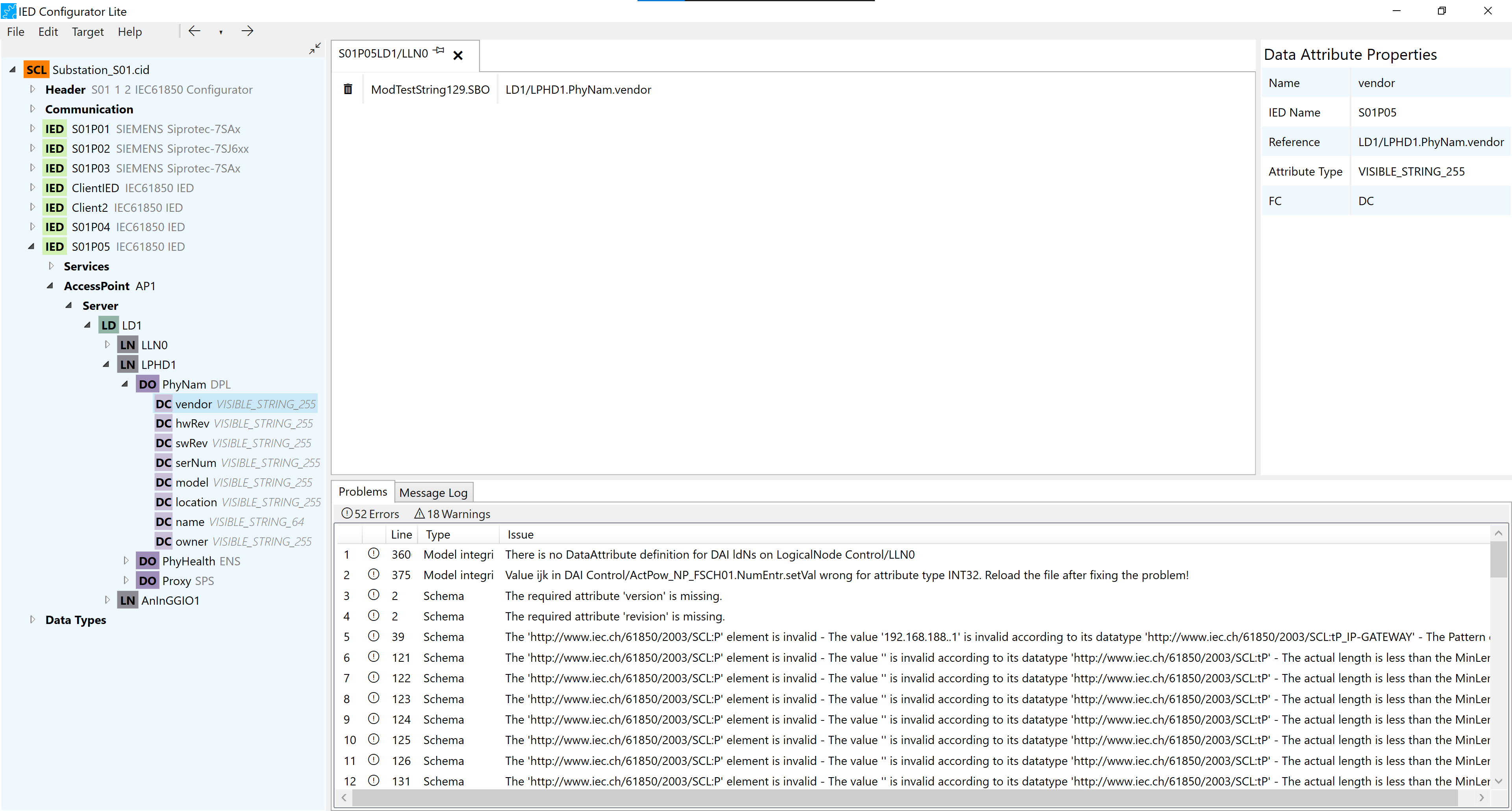
9. Add reference to DAI
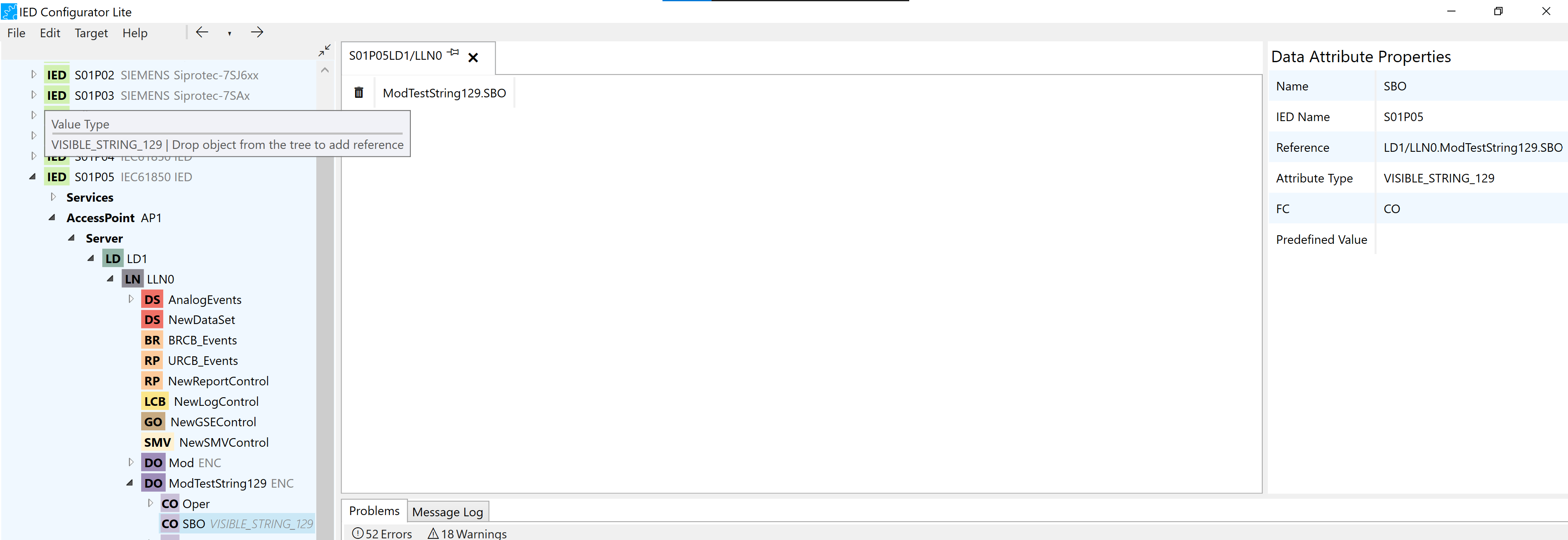
As can be seen in the figure above, in the logical node LLN0 of the IED S01P05 we have a data attribute of type Visible_string_129 named SBO in the data object ModeTestString129. In the predefined values editor, you can add a reference to control by dragging and dropping a data attribute, data object, logical node, logical device, or IED. As can be seen in the next figure, the user has dragged the data attribute LD1/LPHD1.PhyNam.vendor ( DA is shown in the tree view and its properties can be observed in the right side of the window) and the value of DAI has been updated by its reference.
10. Add multi Data Object Predefined Values editor
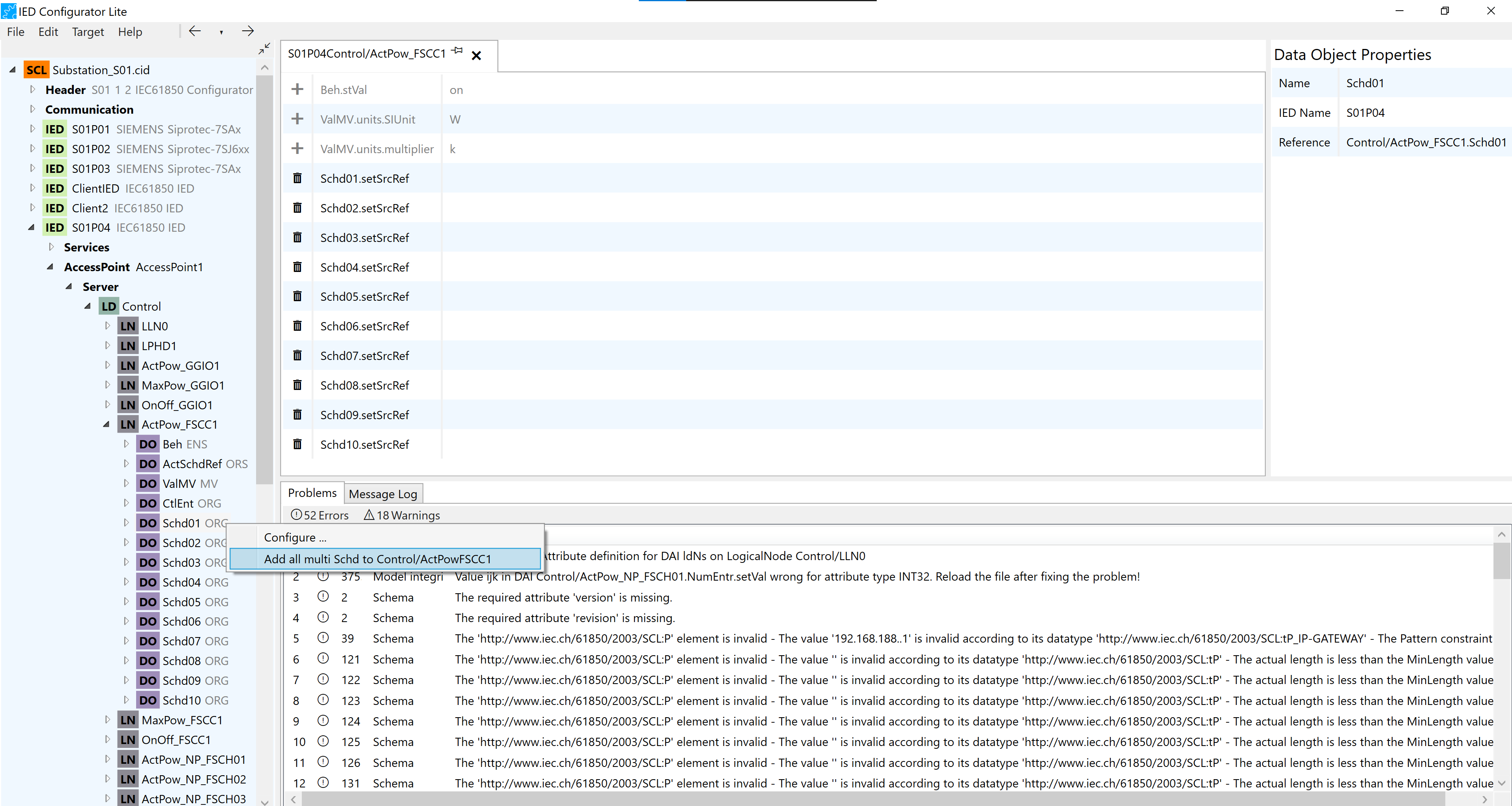
As you can see in the figure above, the logical node ActPow_FSCC1 has a Multi Data Object Schd that consists of ten instances. When you open the Predefined Values Editor for the ActPow_FSCC1 logical node, you can add all the Multi Data Object instances at once by right-clicking on one of the Data Object instances in the tree view and selecting Add all multi. This function is a shortcut for configurations that require adding many data objects at once.